Services

Arc Flash Mitigation

Performing Arc Flash assessment and mitigation is one of the most important actions necessary to increase the safety of employees working around live electrical equipment. it will save lives and equipment. Arc Flashes occurs when the electrical current leaves its normal path and travel through the air from one conductor to another or to ground. This current is called arcing current and can be contributed to may factors, but most common are human accident like dropping tools, worn conductor insulation, exposed live parts, dust, equipment failure and poor maintenance.
We minimized the incident energy released during an arc fault by minimizing its duration.
Most of the times we are able to mitigate arc flash incident energy simply by revising the protective devices overcurrent settings. in some cased we make recommendation for installing additional devices such as current limiters.
We calculate the incident energy and flash boundaries based on requirements of NFPA 70E and IEEE 1584.
We can use ETAP or SKM depending on the client requirements.

Short Circuit

Short-circuit value increases due to load growth and due to increase in the capacity of the of the facility and electric utility power systems. Changes in the configurations of the transmission and distribution system also result is significate changes in the short circuit values.
Therefore, short circuit studies need to occur when power system is originally designed and on a regular basis, at least every 4-5 years.
​​To be in compliance with the national electric code, the short circuit rating of buses and interrupting devices shall be higher than the calculated fault current at the equipment. Short circuit current above the equipment ratings can cause catastrophic losses.
in the study we provide the percentage of rated short circuit current and identify all devices and equipment with insufficient rating.
​Short circuit study is very important because it is the bases for protective device settings and coordination as well as the arc flash study.
Investing in these studies greatly enhances the reliability and safety of the electric power systems. ​
​We can perform the analysis based on ANSI or IEC standards based on the client requirement. ​
We can use ETAP or SKM depending on the client requirements.

Service-E

Power Flow and Voltage Drop Studies

Power Flow study is the starting point in the planning stage for a new power system or a future expansion to an existing system.
We study all operating scenarios and identify overloaded equipment and cables. We determine the active and reactive power, voltage, current, and power factor throughout the power system.
We also exam the performance of the system during maintenance situations. For example, if a transmission line or a transformer is taken off line due to planned maintenance or due to a fault, can the remaining lines or transformers perform safely and can it support the loads without interruption or the need for load sheading.
We note the rating of all electrical equipment such as transformers, cables, switchgears, motor control centers, and distribution panel boards. We identify the percentage of rated load during normal and worst case contingency operation.
​We determine the percentage of rated voltage of all buses during normal and contingency operation and while direct online starting of large motors.
We end the report with conclusions and make recommendations.

Protective device settings and coordination

We perform this study to establish the recommended protection settings for overcurrent and protective devices. We provide time current curve for each protective device to demonstrate that adequate equipment protection and selective device operation is provided
We evaluate the coordination time intervals at the maximum operating short circuit current (clipping current) each relay will experience.
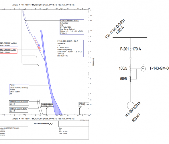
We provide time current curves for single branch circuits, which include the protective device characteristic, motor stating curve (for motor protection), equipment damage curve to illustrate that protection is provided.
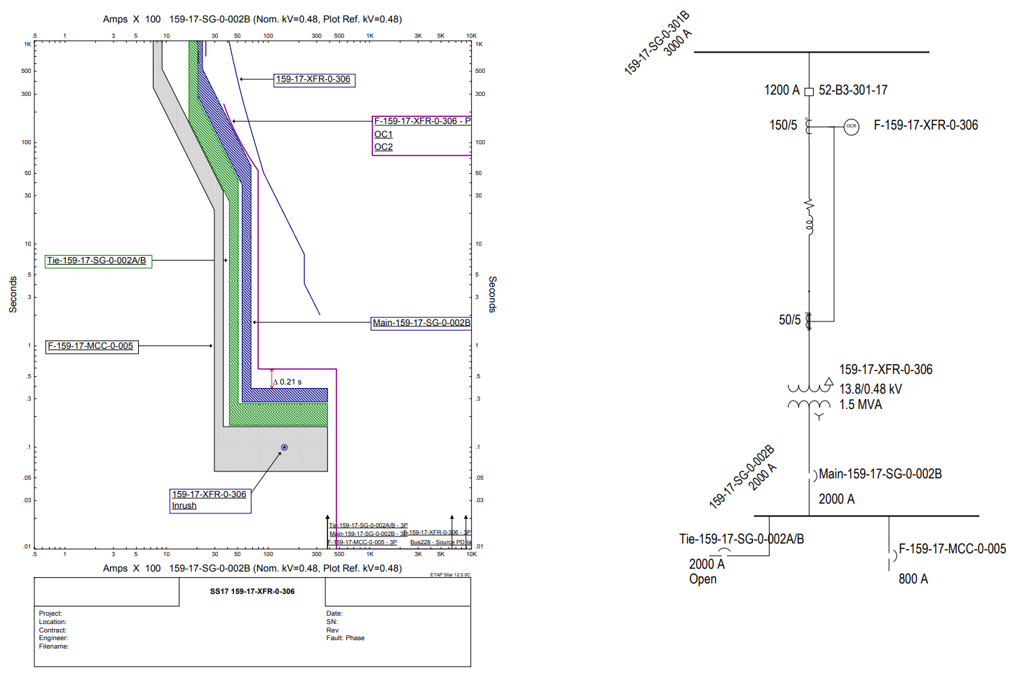
We also provide time current curves that includes multiple devices such as mains, ties, and feeders to show coordination. These curves typically omit starting and damage curves so that the coordination between devices can be most easily interpreted. Devices are selectively coordinated when there is sufficient time allowed between their characteristic curves to ensure the device closest to the fault operates first.
We set the amount of time required to achieve coordinated and selective operation between relay-relay, relay-fuse, etc. based on the recommendations in the IEEE Buff Book, Std. 399.
An interval of 0.20 second is typically used between static overcurrent relays. In selected instances a slightly larger time is used for additional security.
A minimum interval of 0.12 second is generally used between an upstream static overcurrent relay and a downstream low voltage circuit breaker.
When coordinating devices whose characteristic curves both include clearing times and tolerances, the curves must simply not overlap. Such is the case when coordinating low-voltage static trip devices with each other or with modeled-case circuit breakers and fuses.

Motor Starting

We perform static motor starting studies to evaluate the performance of the electrical distribution system during direct-on-line starting of the largest low voltage and medium voltage motors while operating in normal and worst-case contingency conditions. We calculate the voltage at all busses in the electrical system and note any voltage drop below 85% of the nominal voltage.

All analysis and output data are as good as the power system model. Therefore we put a lot of effort in making sure the model is correct before we start the analysis. Many times we have to do a site visit to collect equipment data and operation characteristics needed to model the power system.