Protective Device Settings and Coordination
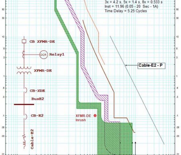
We perform this study to establish the recommended protection settings for overcurrent and protective devices. We provide time current curve for each protective device to demonstrate that adequate equipment protection and selective device operation is provided
We evaluate the coordination time intervals at the maximum operating short circuit current (clipping current) each relay will experience.
We provide time current curves for single branch circuits, which include the protective device characteristic, motor stating curve (for motor protection), equipment damage curve to illustrate that protection is provided.
We also provide time current curves that includes multiple devices such as mains, ties, and feeders to show coordination. These curves typically omit starting and damage curves so that the coordination between devices can be most easily interpreted. Devices are selectively coordinated when there is sufficient time allowed between their characteristic curves to ensure the device closest to the fault operates first.
We set the amount of time required to achieve coordinated and selective operation between relay-relay, relay-fuse, etc. based on the recommendations in the IEEE Buff Book, Std. 399.
An interval of 0.20 second is typically used between static overcurrent relays. In selected instances a slightly larger time is used for additional security.
A minimum interval of 0.12 second is generally used between an upstream static overcurrent relay and a downstream low voltage circuit breaker.
When coordinating devices whose characteristic curves both include clearing times and tolerances, the curves must simply not overlap. Such is the case when coordinating low-voltage static trip devices with each other or with modeled-case circuit breakers and fuses.

